In a previous note – CDLN 2014:008 – I described the digital capture of cylindrical objects in order to create digital rollouts. This method was used primarily for the capture of cylinder seals as an alternative to the black and white photography of modern seal impressions used for seals catalogues. There is good evidence for other cylindrical objects among the artefacts of the ancient Near East as well. This short note deals with the capturing of a particular cylindrical object and combining this effort with Reflectance Transformation Imaging (RTI), which allows for the manipulation of the light angle cast onto the object. A similar approach on cylinder seals will be dealt with in a separate note.
In November 2014 the latest dome built by Kirk Martinez and Philip Basford at the Electronics and Computer Science Department (ECS) of the University of Southampton was shipped to Norway in order to use it on cuneiform artefacts in the Schøyen collection. The collection has been digitised through photography and scans in the past, but images taken by a camera dome are clearly superior to any conventional image.
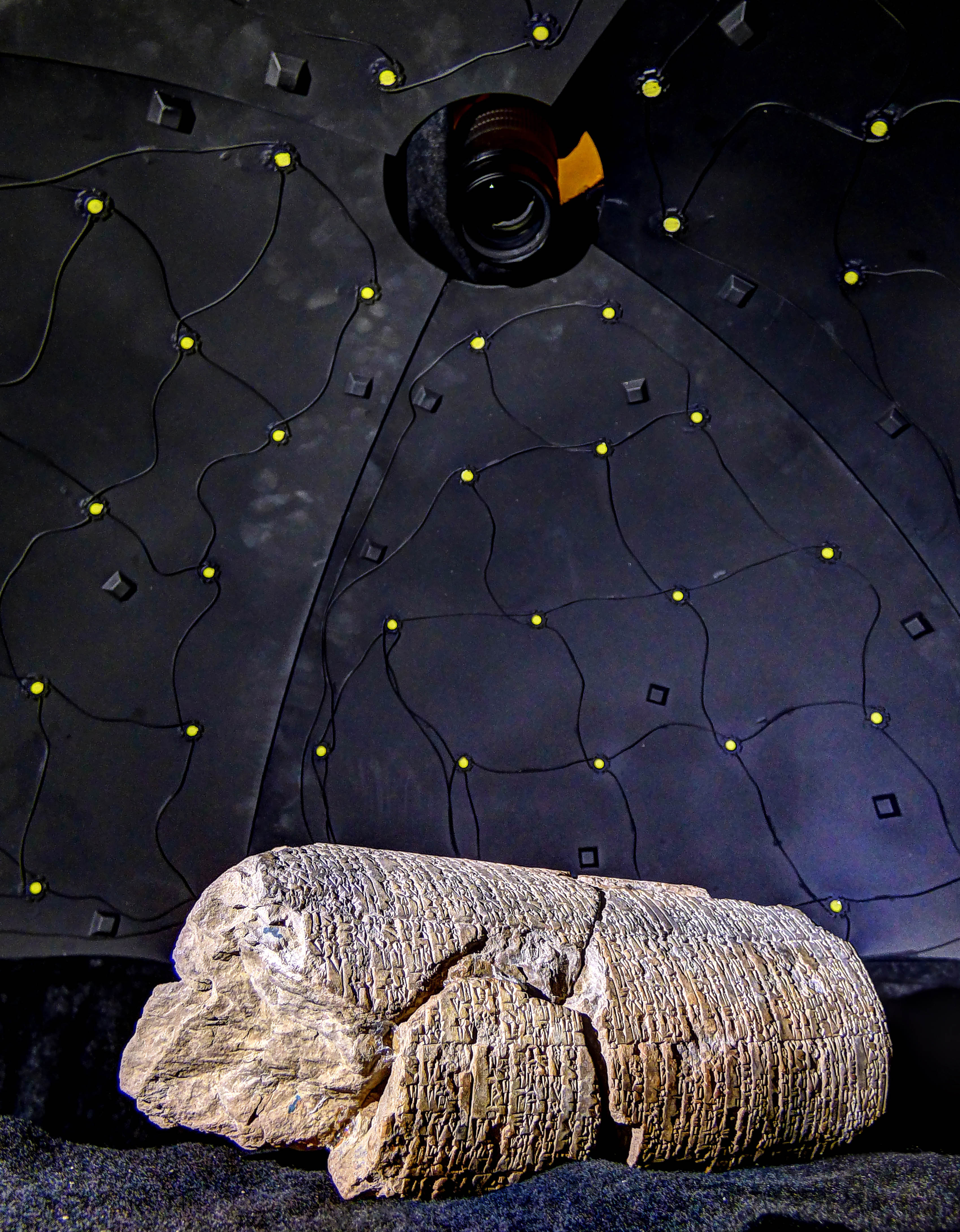
Among the many objects that were captured in the camera dome was one extraordinary piece, which was edited by Miguel Civil as CUSAS 17, 107 (Civil 2011). MS 2064 is a large clay cylinder with partly broken surface containing a composition known either as “The Law Collection of Ur-Namma”, “Codex Ur-Namma” or “Ur-Namma Law Code”. The prologue of this composition was already known through other manuscripts and therefore incorporated by Douglas R. Frayne as RIME 3/2.01.01.20 (Frayne 1997: 43-49). Claus Wilcke mentioned the cylinder in his reconstruction of the composition, but could not include it there (Wilcke 1990: 292; see the score transliteration).

Fig. 1: MS 2064 in the camera dome
Capturing cylindrical objects requires time, since enough turns of the cylinder are needed in order to create a sufficient amount of control points between the various angles. The cylinder MS 2064 was turned 26 times to cover all angles of the inscribed surface. Problems arise with the fact that the cylinder is broken and therefore the support needs to be adjusted in order to compensate for the varying height. A high F-stop was used in order to increase the Depth-of-Field (DoF) and reduce blurriness outside the main focus area.
Fig. 2 shows a small selection of images taken by the camera dome. Each angle produces 76 high-resolution images, which are saved in a folder called “original-captures”

Fig. 2: A selection of original dome captures of one view
The next step in producing a digital rollout was to choose one image per set, which shows the cylinder as complete as possible. Therefore an image was chosen that was taken using a rather high light angle; this involves LEDs within the dome, which are close to the dome's zenith. For the dome used in Norway image 56 proved to be the best choice. Fig. 3 contains a selection of this particular LED in various viewing angles.

Fig. 3: A selection of image 56 in various viewing angles
Next we use this image from every single viewing angle – 26 in total – as source images for the stitching software PTGui Pro (Fig. 4). It is worthwhile to rename all original captures and move them into one working folder in order to improve the workflow. For image 56 the new file name would be: “56A.jpg”, “56B.jpg”, “56C.jpg”, “56D.jpg”, “56E.jpg”, “56F.jpg”, etc. (or using a RAW format). The great advantage of the software PTGui Pro is the capability to save the settings for each stitching process as a template, which means that the source images can be exchanged by others (see below). This will be very important for creating the final source images or “original captures” for the Polynomial Texture Map (*.ptm).

Fig. 4: Loading the array of source images into PTGui Pro
The partly broken surface makes a clear stitching without any manual adjustments difficult. Fortunately, the software allows for a plentitude of manual settings as, for instance, placing control points between images manually and masking specific areas on single images in order to omit them in the stitching process. This is particularly important for partly broken cylinders, since the break lies beneath the actual – for the stitching process relevant – surface and the perspective changes between every single viewing angle (Fig. 5).

Fig. 5: Masking and omitting certain areas in the stitching process
Control points are usually created automatically while the software tries to align the various source images. However, difficult objects such as MS 2064 require moderate manual effort to place additional control points manually (Fig. 6a and 6b).


Fig. 6a and 6b: Control points between single viewing angles
The next step is to let the software align all images based on the settings for masking as well as the control points and see whether the settings need any further adjustments.
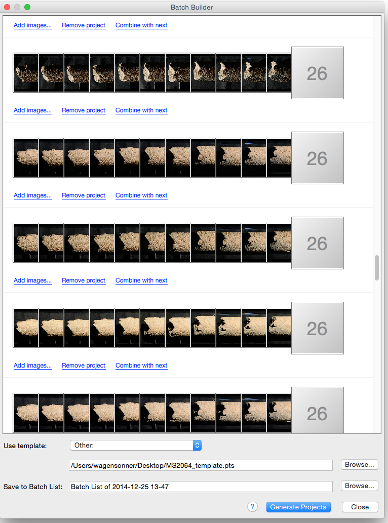
If the stitching was successful, the current settings can be applied to other arrays of source images. In order to do that, we need to save these settings as a template. PTGui Pro allows to use the same stitching settings for different arrays of source images. Although a different set of source images (for instance, all viewings angles that use LED 43) can be loaded into the software and aligned according to the saved template, PTGui Pro offers the useful tool of a “batch builder”, which allows for creating stitching projects based on the 26 arrays of original captures automatically (Fig. 7a and 7b).


Fig. 7a and 7b: The batch stitcher in PTGui Pro
At this stage it becomes important that all images had been renamed in a certain pattern in order to feed them into the PTGui's batch builder correctly. Once the batch process has finished the result are 76 stitched images, which conform to the same light positions as the original viewing angles (Fig. 8).

Fig. 8: The array of files after batch processing in RTIbuilder
These 76 images can now be taken as “original captures” for creating a new Polynomial Texture Map. However, as mentioned earlier, the stitching of a broken cylinder leaves problematic areas, which are due to the change of perspective while rotating the cylinder in the camera dome.
Any changes need to be applied to every single stitched image. For that purpose Adobe Photoshop and its capability to save Actions comes in quite handy. Similar to the templates in PTGui Pro these actions can be applied to any number of images.
Rollouts of cylindrical objects represent the surface on a two-dimensional plain. Nevertheless, it is worthwhile to retain the original shape of the cylinder. In order to do that, to each stitched image a complete representation of the cylinder as well as the top and bottom sides should be added. This can again be achieved by using Photoshop actions.
Fig. 9: The final result of MS 2064 (animated GIF)
Please click on image in order to be able to adjust the light angle manually
The final result (Fig. 9) is a complete representation of the cylinder. The broken areas had not been captured in the dome. For those areas conventional High Dimension Range (HDR) photos can be used and blended into each original capture as static image, if needed.
Since the inscription is of main concern for the end result and the stitching software naturally has issues with the change of perspective in the broken areas, just the inscribed area has been cut out and blended into the static HDR image.
| Civil, Miguel | ||
| 2011 | “The Law Collection of Ur-Namma”. In: A. George (ed.) Cuneiform Royal Inscriptions and Related Texts in the Schøyen Collection (CUSAS 17; CDL Press: Bethesda, MD):221-286. | |
| Frayne, Douglas R. | ||
| 1997 | Ur III Period (2112–2004 BC), RIME 3/2. University of Toronto Press: Toronto, Buffalo & London. | |
| Wilcke, Claus | ||
| 2002 | “Der Kodex Urnamma (CU): Versuch einer Rekonstruktion”. In: T. Abusch (ed.) Riches Hidden in Secret Places. Ancient Near Eastern Studies in Memory of Thorkild Jacobsen (Eisenbrauns: Winona Lake, Indiana):291-333. | |


